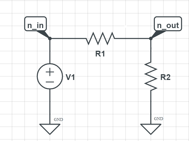
Example 1: RESISTIVE DIVIDER#
Authors: Sania Dolat, Ali Saadatpour
Contacts: , qstzen@proton.me
Brief overview of the resistive divider#
A resistive divider, also known as a voltage divider, is a simple circuit that uses resistors to reduce the voltage to a desired level. It is a fundamental concept in electronics, often used to create reference voltages or to measure voltages using analog-to-digital converters (ADCs).
Basic Principle#
The resistive divider consists of two resistors connected in series. The input voltage is applied across the series combination, and the output voltage is taken from the junction between the two resistors. The output voltage \(V_{out}\) is a fraction of the input voltage \(V_{in}\), depending on the values of the resistors.
Voltage Divider Formula#
Given two resistors \(R_1\) and \(R_2\) in series, the output voltage \(V_{out}\) can be calculated using the following formula: $\( V_{out} = V_{in} \times \frac{R_2}{R_1 + R_2} \)$
Applications#
Reference Voltage: Used to generate a specific voltage reference from a higher voltage.
Biasing: Commonly used to set the operating point of transistors.
Signal Attenuation: Reduces the amplitude of a signal for measurement or interfacing with lower voltage circuits.
Example Calculation#
Suppose you have a \(12V\) input voltage \(V_{in}\) and you want to create a \(5V\) output. If \(R_2 = 10k\Omega\), you can find \(R_1\) as follows:
Solving for \(R_1\):
Thus, using \(R_1 = 14k\Omega\) and \(R_2 = 10k\Omega\) would give you a \(5V\) output from a \(12V\) input.
Would you like to explore more about resistive dividers, such as their use in specific circuits or practical considerations like loading effects?
Start Programming#
We will work on the following circuit

Logging information about the simulation.
This shoud be always imported.
import PySpice.Logging.Logging as Logging
logger = Logging.setup_logging()
Imports#
from PySpice.Spice.Netlist import Circuit  #used for creating circuit
from PySpice.Unit import *  #used for unit usages like ohm, volt, etc
from PySpice.Spice.Library import SpiceLibrary
from PySpice.Spice.Netlist import SubCircuit
import numpy as np
import matplotlib
import matplotlib.pyplot as plt
Output of code#
For styling the output circuit we use the code below
matplotlib.rcParams.update({'font.size': 14,
                            'text.usetex': True,
                            'mathtext.fontset': 'cm',
                            'mathtext.rm': 'serif'})
Making circuit#
First we need to make a circuit instance. I name this circuit the “Resistive Divider”. You can name it whatever you want.
circuit = Circuit('Resistive Divider')
Complete Components#
Then we need to add some components to the circuit.
circuit.V(1, 'n_in', circuit.gnd, 10@u_V)
circuit.R(1, 'n_in', 'n_out', 2@u_kOhm)
circuit.R(2, 'n_out', circuit.gnd, 3@u_kOhm)
Resistor R2
Explanation#
The first parameter is the name of the component;V1, R1, R2 for instance. The second parameter is one side of the component that connect to the positive node. The third parameter is one another side of the component that connect to the negetive node. The last parameter is the value of the component; 10v, 2kohm, 3kohm for instance. Note that instead of circuit.gnd you can put 0 for simplicity.
Let’s print the netlist so far to see the circuit information.
print(circuit)
.title Resistive Divider
V1 n_in 0 10V
R1 n_in n_out 2kOhm
R2 n_out 0 3kOhm
Simulator creation#
We need to create the simulator object
simulator = circuit.simulator(temperature=25, nominal_temperature=25)
print(simulator)
.title Resistive Divider
V1 n_in 0 10V
R1 n_in n_out 2kOhm
R2 n_out 0 3kOhm
.options TEMP = 25C
.options TNOM = 25C
.end
Simulatio start#
This is the full netlist of the circuit we have just created.
After simulation we go through cicuit analysis. The analysis process saves all the node voltage, current and etc.
analysis = simulator.operating_point()
Printing nodes voltage#
For example we want to see the voltage of each node
for node in analysis.nodes.values():
  print(f"Node{str(node)}: {float(node)}V")
Noden_out: 6.0V
Noden_in: 10.0V
C:\Users\Hadi\AppData\Local\Temp\ipykernel_7028\4014887527.py:2: DeprecationWarning: Conversion of an array with ndim > 0 to a scalar is deprecated, and will error in future. Ensure you extract a single element from your array before performing this operation. (Deprecated NumPy 1.25.)
  print(f"Node{str(node)}: {float(node)}V")
Specific node observation#
For simple voltage analysis for specific node you can use the code below
print(float(analysis.nodes['n_in']))
10.0
C:\Users\Hadi\AppData\Local\Temp\ipykernel_7028\2323803351.py:1: DeprecationWarning: Conversion of an array with ndim > 0 to a scalar is deprecated, and will error in future. Ensure you extract a single element from your array before performing this operation. (Deprecated NumPy 1.25.)
  print(float(analysis.nodes['n_in']))
Accessing to the Branches#
For current analysis of each branch we can write
for branch in analysis.branches.values():
  print(f"Branch{str(branch)}: {float(branch)}A")
Branchv1: -0.002A
C:\Users\Hadi\AppData\Local\Temp\ipykernel_7028\1718386672.py:2: DeprecationWarning: Conversion of an array with ndim > 0 to a scalar is deprecated, and will error in future. Ensure you extract a single element from your array before performing this operation. (Deprecated NumPy 1.25.)
  print(f"Branch{str(branch)}: {float(branch)}A")
Specific Brach#
And for the specific branch we have
print(float(analysis.branches['v1']))
-0.002
C:\Users\Hadi\AppData\Local\Temp\ipykernel_7028\2415665817.py:1: DeprecationWarning: Conversion of an array with ndim > 0 to a scalar is deprecated, and will error in future. Ensure you extract a single element from your array before performing this operation. (Deprecated NumPy 1.25.)
  print(float(analysis.branches['v1']))
Note#
In PySpice the positive current happens when the current flows from posistive to negetive voltage source(completely oposite of what we just expected).
